Tetra hardware: Difference between revisions
No edit summary |
(add a link back to main tetra page) |
||
| (2 intermediate revisions by one other user not shown) | |||
| Line 1: | Line 1: | ||
The tetra hardware is based on the Broadcom BCM23550 (referred to as ''java'' in the device tree) chipset. | The [[Tetra|tetra]] hardware is based on the Broadcom BCM23550 (referred to as ''java'' in the device tree) chipset. | ||
[[File:Front of tetra main board.jpg|alt=Front of tetra main board|thumb|Front of tetra main board]] | [[File:Front of tetra main board.jpg|alt=Front of tetra main board|thumb|Front of tetra main board]] | ||
[[File:Front of tetra main board NFC antenna removed.jpg|alt=Front of tetra main board NFC antenna removed|thumb|Front of tetra main board NFC antenna removed]] | [[File:Front of tetra main board NFC antenna removed.jpg|alt=Front of tetra main board NFC antenna removed|thumb|Front of tetra main board NFC antenna removed]] | ||
| Line 6: | Line 6: | ||
[[File:Back cover of tetra.jpg|alt=Back cover of tetra|thumb|Back cover of tetra]] | [[File:Back cover of tetra.jpg|alt=Back cover of tetra|thumb|Back cover of tetra]] | ||
=== Front === | === Front PCB === | ||
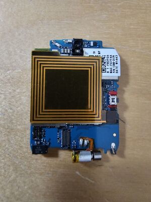
The front of the PCB is covered by a flexible PCB antenna used for NFC. This is connected to the PCB via a U.FL connector. | The front of the PCB is covered by a flexible PCB antenna used for NFC. This is connected to the PCB via a U.FL connector. | ||
| Line 15: | Line 15: | ||
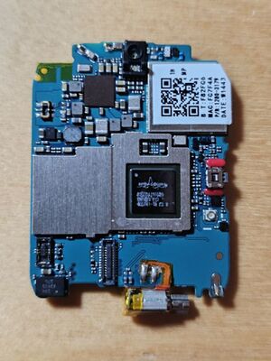
The unmarked chip on the top left is most likely the bcmpmu (Broadcom Power Management Unit). | The unmarked chip on the top left is most likely the bcmpmu (Broadcom Power Management Unit). | ||
=== Back === | The vibrator motor is permanently soldered on the front PCB. The back has kapton tape to avoid short circuiting against the metal bottom case. | ||
=== Back PCB === | |||
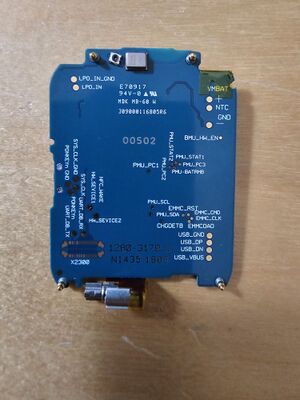
The back of the PCB has testpoints, pogo pins and space for an unpopulated connector. | The back of the PCB has testpoints, pogo pins and space for an unpopulated connector. | ||
=== Casing === | |||
The case is closed via four screws and a silicone like glue. | |||
The front part consists of the LCD and a transparent part for the ambient light sensor. | |||
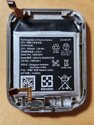
The back part contains a epoxied micro USB connector and a (lightly) glued in 1.59Wh battery. | |||
Latest revision as of 12:49, 11 August 2024
The tetra hardware is based on the Broadcom BCM23550 (referred to as java in the device tree) chipset.
Front PCB
The front of the PCB is covered by a flexible PCB antenna used for NFC. This is connected to the PCB via a U.FL connector.
Removing the NFC antenna reveals the Broadcom SoC and on its left a shield on top of the memory.
The shield with a QR code is covering the BCM43341 Bluetooth/WiFi chip.
The unmarked chip on the top left is most likely the bcmpmu (Broadcom Power Management Unit).
The vibrator motor is permanently soldered on the front PCB. The back has kapton tape to avoid short circuiting against the metal bottom case.
Back PCB
The back of the PCB has testpoints, pogo pins and space for an unpopulated connector.
Casing
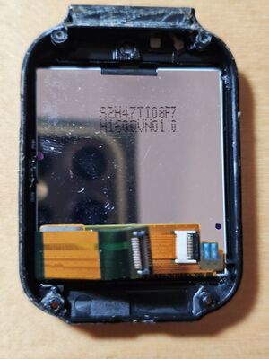
The case is closed via four screws and a silicone like glue.
The front part consists of the LCD and a transparent part for the ambient light sensor.
The back part contains a epoxied micro USB connector and a (lightly) glued in 1.59Wh battery.
